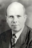
History: From Windom Antenna to Multiband OCFD
This history section has turned out quite lengthy, to the point that it has become almost an article within an article. However, if you are not interested in the history of this antenna, you may easily skip this section. The working principle of the new CL-OCFD has been fully explained in the previous sections.
This section is currently in the process of being rewritten. I apologise for this unconvenience. Nonetheless I opted to share the latest unfinished revision of this text here with you. This way you will have the most complete information at hand.
Introduction
The Windom antenna, one of the oldest antennas developed for amateur use, has had a complicated history, one as interesting as the theory of the antenna itself.
Nowadays there is much confusion to what is to be understood under the term Windom antenna. Purists, like the late L. B. Cebik, W4RNL (°1939 - †2008) and myself included, would employ the term Windom antenna only for a dipole fed by a vertical single-wire transmission line connected at an off-center location of the dipole such that the Standing Wave Ratio (SWR) on the vertical wire is low. By consequence, the vertical wire will not radiate and the current distribution on the horizontal wire section will be undisturbedly sinusoidal. I will call this antenna the archaic Windom antenna.
Conversely, when fed at an inappropriate off-center position, the vertical wire would radiate and the current distribution on the horizontal wire would show a jump. This
However, over the years, the term Windom antenna has been laden to include off-center-fed dipole antennas fed by symmetrical open ladder line and coaxial cable via a balun. In this case, the current distribution on the horizontal wire can never be disturbed by the connecting feed line. I will call this antenna the off-center-fed dipole or reluctantly succumbing to prevailing habits, the modern Windom antenna.
Some of the historical data on the Windom antenna was obtained from Paul Rockwell, W3AFM, who very kindly made his files available to me. I would like to thank Messers Everitt, Ryder, Byrne, and Windom, who very kindly made extensive comments on a draft of this article.
I do not tend to do this very often
By John J. Nagle, K4KJ (SK) of Herndon, Virginia
Early History: Single-Band, Single-Wire Feeding
The single-wire feedline has been credited to Frank Conrad, 8XK, of Westinghouse. He used it in the broadcast band to feed a quarter-wavelength grounded vertical antenna, then also known as Marconi antenna.
In that era, electrically-asymmetrical antennas that used the ground, a groudplane or counterpoise were called Marconi antennas. Conversely, electrically-symmetrical antennas, such as an ordinary dipole, were called Hertz antennas.
A next step was taken by V. D. and E. B. Landon, 8VN, who connected the single feedwire to the junction of an inverted L-antenna and a less radiating, folded so-called «counterpoise». (See also L. B. Cebik’s article on the use and the abuse of the word counterpoise.)
In a later article by Howard M. Williams, 9BXQ, the «counterpoise» was stretched out horizontally and made part of the radiating antenna with the feedpoint still off-center.[4] This latter antenna can be considered as the first authentic Windom antenna. Fig. 1 shows a summary of these three stages of early development.
In the middle 1920s Loren Windom operated 8GZ/8ZG in the Columbus, Ohio, area. Windom ran high power for that time (250 watts) and was considered the technical bellwether of Columbus hams, as he was an active experimenter, working with antennas among other things.
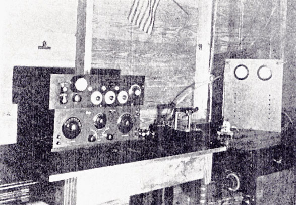
The 8GZ shack in 1923 comprising a Grebe CR-3 detector with a two-step audio amplifier and Brandes phones. The transmitter was a 50W reversed feedback circuit with series-plate supply.
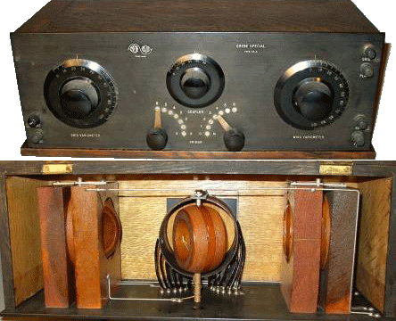
Grebe CR-3 detector
In July, 1926, the technical editor of QST, Robert S. Kruse, published an article which gave a roundup of various methods of feeding an antenna as they were understood at that time.[5] A discussion by Windom on how to adjust the off-center-fed antenna was a part of that article; the procedure consisted of placing a light bulb in the center of the antenna and adjusting the feedpoint for maximum lamp brilliance (maximum current). This procedure was also published in the first three editions of the ARRL Radio Amateur’s Handbook.
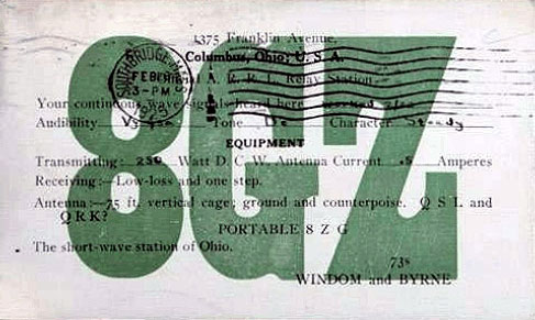
8GZ QSL card carrying the names of Windom and Byrne
John Byrne, then 8DKZ, became associated with Windom; 8GZ/8ZG QSL cards, circa 1925, carried the names of both Windom and Byrne. Both were students at Ohio State University — Byrne in electrical engineering and Windom in law.
It was customary in those days for senior engineering students to do a thesis for graduation; Byrne and his thesis partner, E. F. Brooke, 8DEM, chose the single-wire transmission line as their topic. They carried out a considerable amount of research on the subject under the guidance of their faculty advisor, William Littell Everitt (°1900 - †1986), who was then Associate Professor of Electrical Engineering. Everitt will be remembered for his book, Communication Engineering, which was the standard college textbook on the subject in the 1930s and early 1940s.
Windom, although not formally associated with the project, assisted from time to time in rigging or making measurements on his lunch hour or after classes, so he was up-to-date on the progress of the work. In fact, he incorporated many of the more promising facets at his own station.
Byrne’s investigation was incomplete when he graduated in June, 1927; however, he returned as a graduate student for the 1927-28 academic year and continued work on the single-wire feeder as his Master’s thesis with A. B. Crawford as his partner. The work thus accomplished was published in the Proceedings of the IRE in October, 1929, with Everitt and Byrne listed as authors. It was standard practice then, as now, that when a student’s research work is formally published, the faculty advisor is listed as senior author.
The work of Everitt, Byrne and Brooke showed that the Windom procedure of 1926 was incorrect. Windom agreed in his 1929 article, and stated that his earlier method should not be used; he went on to describe the Everitt-Byrne method that I will explain later. Beginning with the seventh edition of the ARRL Handbook, the old, Windom graphs for the single-wire feeder were presented which give the length of the antenna as a solid line and the location of the tap as a dashed line for each amateur band. The Everitt-Byrne procedure has not been published in any of the ARRL handbooks or antenna manuals and is not widely known.
Windom recognized the utility of the method to the amateur community and encouraged Byrne to write it up for QST. Byrne declined, suggesting that Windom write it up himself as Windom was familiar with the work. Windom’s article was published in the September, 1929, issue of QST[2] a month before the Everitt-Byrne article. The delay in the Everitt-Byrne paper is ascribed to the more extensive editorial review required by the Proceedings of the IRE; Windom, to his credit, stated in an early paragraph that he had not done any of the work himself — that he was only reporting the work of others. The fact that Windom’s article was published a month before the Everitt-Byrne paper did cause considerable consternation, however.
Byrne, having completed his studies, turned the project over to John Ryder, W80QZ. Ryder was later to become Professor of Electrical Engineering at Michigan State University and the author of numerous electronics textbooks (he is not the Rider of Rider’s Manuals fame). When Byrne left Ohio State University, he went to work at Bell Telephone Laboratories and gave up amateur radio. I cannot help but feel that amateur radio lost a valuable member by this decision.
The first use of the name "Windom" appears to be by the Wireless Institute of Australia which in 1930 published an article which was substantially a reprint of Windom’s QST article. Shortly after World War II, the Radio Society of Great Britain ran an article, "Why Not a Windom?" It thus appears that the name Windom was imported into the United States from overseas. Rightly or wrongly, the name has stuck because it is much simpler than the more technical term, "off-center-fed Hertz antenna."
During the years 1923 to 1925, several single-wire-fed antennas (both horizontal and vertical) were being described in the ARRL’s QST magazine. What made these antennas particularly interesting, was the fact that their single-wire feedline, with a characteristic impedance of about 500Ω, could be easily matched to the valve amplifier end-stages of that time.
In October 1929, after some years of research, William L. Everitt (°1900 - †1986) and J. F. Byrne, both of the Ohio State University, published in the prestigious Proceedings of the IRE an exact method to tune the antenna to resonance and to match the single-wire feedline in order to prevent radiation from the latter. John D. Ryder, at that time student of Everitt, carried out many of the antenna measurings, according to an interview he gave in 1972.
However, Loren Windom, W8GZ, was first to reveal the antenna to the greater radio amateur community by elaborately describing the antenna in the September 1929 issue of QST. It was by Windom’s name that the antenna got known outside the USA.
So far, the Windom antenna (see figure below) was an off-center-fed resonant dipole with a single-wire feedline of any length-fed against earth and intended to be used on one frequency only. Its main advantages were its single-wire feedline —would not be of any value anymore today because of propensity to cause RFI— and the fact that it could be easily matched to a valve amplifier.
Interlude: First Harmonic Multiband Use
In 1937, VS1AA was first to describe a multiband archaic Windom (see table in next section for dimensions). The antenna could be employed on 80, 40, 20 and 10m with considerable, though acceptable levels of VSWR. Feeding was still done over a single-wire, matched with a Collins-filter to a valve amplifier.
Recent History: Coaxial Feeding
What became perhaps the most popular multiband Windom design of all, was the German-made Fritzel FD4 antenna, described by the late Dr. Fritz Spillner, DJ2KY, in 1971[1]. It had the same dimensions as the VS1AA multiband Windom antenna, but fitted with a 300Ω balun at its feed point and-fed over coax. Purists would not call this a Windom antenna anymore because of the absence of the single-wire feedline. The term off-center-fed (OCF) dipole is preferred.
Over in the United States, interest in the archaic Windom antenna was again revived, lead by the 1978 article in Ham Radio Magazine written by John Nagle, K4KJ (SK)[2].
Today, many radio amateurs keep on using multiband Windom antennas with more than satisfactory results. It is not without reason that Windom antennas are being employed at the IARU HF World Championships! Nonetheless, the attention for this type of antenna diminished somewhat over the years, especially with younger amateur radio operators. Perhaps many young hams ignore the multiband Windom antenna because of its sheer simplicity (like I did for some time) and may be considering it to be too good to be true. The complexity of feeding the G5RV, the losses in multiband trap antennas and the esotheric marketing of some other questionable antenna designs ununderstandably seem to appeal more.
This article sets out to continue the tradition of the multiband Windom antenna, however by taking a careful look at its design with the latest, though proven, computer modelling techniques.
The Next Step: Center-Loading
Better Harmonic Matching throughEpilogue
The people who have contributed to the development of this antenna are -to say the least- intriguing:
Frank Conrad, 8XK, who started it, is called the father of broadcasting. His amateur station became KDKA in Pittsburgh, the first broadcasting station in the country.
Vernon D. Landon, one-half of 8VN, went on to become an eminent scientist with RCA. He has contributed widely to the advancment of electronics with his many very readable papers published in the Proceedings of the IRE and in the RCA Review.
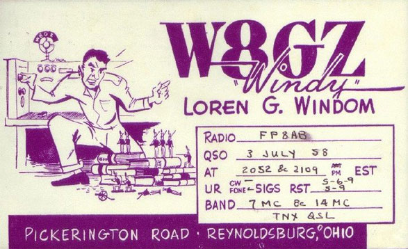
Loren G. «Windy» Windom, W8GZ QSL card
Loren "Windy" Windom, W8GZ, for whom the antenna was named, did not, oddly enough, pursue electronics professionally, but became a lawyer in Ohio. Windom then serving 1940-45 commander of the 145th Infantry. Later on the 37th Adjutant General of Ohio in 1959, appointed by governor. He always remained an active amateur.
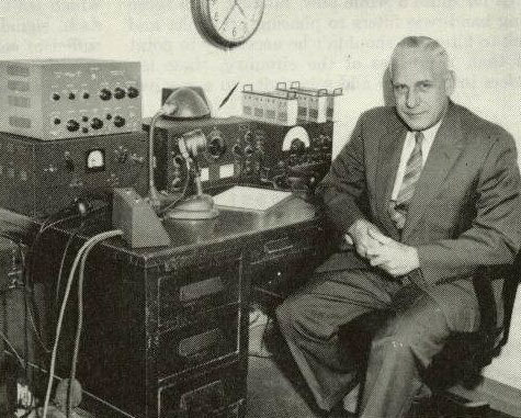
General Loren Windom, W8GZ, in his shack in 1957
John Byrne, who with his thesis partners, E. F. Brooke and A. B. Crawford, did much of the actual work on developing the antenna, became an outstanding research engineer and educator.
John Ryder, K4IHX (SK), who also worked on the antenna as a thesis project, was to become a well-known educator, an author of several electronics textbooks, and a president of the IRE. He was a very active amateur in Florida.
William L. Everitt, as faculty advisor to the students who worked on the antenna, contributed much to its development. Everitt began his amateur career in 1914 as 2ABI; in 1921 he became 8CRI. When he decided to go into communications professionally, he dropped amateur radio because he did not want to have the same vocation and avocation. Everitt was later to become a prominent author and educator. He retired as Dean of Engineering at the University of Illinois and went on to become Dean Emeritus at that university.
Unfortunately, Dr. Everitt has been ill-treated by the amateur community. His work on the off-center-fed antenna is largely unknown and certainly unrecognized.
Unhappily, the same thing happened to him a second time. Everitt was the first to describe the use of a pi network as a coupling device. He published this work in the Proceedings of the IRE in 1931 12 and in Communications;13 the pi network is also described in his book, Communication Engineering. 14 Arthur Collins, W9CXX, of Cedar Rapids, Iowa, recognized the advantages of the pi network to couple the output stage of a transmitter to a transmission line, and used it in his transmitters. This application played an important part in establishing the reputation that Collins equipment will load up to "anything." Collins described the pi network to the amateur community in a QSTarticle15 and in a similar article Radio,16 and the network became known by old-timers as the "Collins Coupler" instead of, perhaps, the "Everitt Easy Loader."
« I believe these are excellent examples of how people who have made notable contributions to the advancement of electronics developed their interest in electronics through amateur radio. It would be interesting to be able to look into a crystal ball to see how the many young people who are today joining the ranks of amateur radio through high school science classes, or as CBers, will go on to make significant contributions to future electronics. »
John J. Nagle, K4KJ (SK)
Herndon, Virginia
May 1978 in Ham Radio Magazine
References
- John J. Nagle, "Windom antennas," Ham Radio, Greenville NH, May 1978, pp.10-19
- 1 w. L. Eventt, and J. F. Byrne, "Single-Wire Transmission Lines for ShOrl·Wave Antennas:' Proceedings of the IRE, October, 1929, page 1840 IA more detailed version of this paper was published by The Engineer· ing Experiment Station, Ohio State University as Bulletin No. 52, February, 19301
- 2 L. G. Windom, W8GZ/W8ZG, "Notes on Ethereal Adornments," OST, Vol. XIII, No.9, September, 1929, pp. 19-22.
- 3. V. O. and E. B. Landon, 8VN, "Capacity Coupling to Operate the Anten· na at its Fundamental," OST, June, 1923, page 22.
- 4. Howard M. Williams, 9BXQ, "The Herlz Antenna at 20 and 40 Meters," as T, July, 1925, page 24.
- 5. Robert S. Kruse, "Feeding the Antenna:' OST, July, 1926, page 11.
- 6. John O. Kraus, Antennas, McGraw-Hili, New York, 1950, page 147.
- 7. The Radio Antenna Handbook, edited by Frank C. Jones and W. W. Smith, 1936, page 32.
- 8. William B. Wrigley, "Impedance Characteristics of Harmonic Anten· nas," OST, February, 1954. page 10.
- 9. Paul Rockwell, W3AFM, "Further on the Windom," 73, August, 1963, page 76.
- 10. John J. Nagle. "Impedance Measurements at RF," CO, Vol. 30, No 11, November, 1974, pp. 18·24.
- 11. R. A. Hubbs, W6BXI, and A. F. Doting, W6NKU, "Accurate RX Noise Bridge:' ham radio, February, 1977, page 10.
- 12. W. L. Everitt, "Output Networks for Radio·Frequency Power Amplifiers," Proceedings of the IRE, May, 1931, page 725.
- 13. W. L. Everitt, "Coupling Networks," Communications, Septem· ber, 1938.
- 14. W. L. Everitt, Communication Engineering, McGraw-Hili, New York, 1937, page 263
- 15. A. A. Collins, W9CXX, "A Universal Antenna Coupling System for Modern Transmitters," OST, February, 1934, page 15,
- 16. A. A. Collins, W9CXX, "The Answers to the Flood of Inquiries Regarding the Collins Antenna System:' Radio, March, 1934, page 5,
- Fritz Spillner, DJ2KY, "Die FD4-Windom-Antenne," QRV, Stuttgart, 25, Dezember 1971, pp.13-20
