
Common Mode Chokes
Serge Stroobandt, ON4AA
Copyright 2013–2020, licensed under Creative Commons BY-NC-SA
- Home
- Antenna Components
- Common Mode Chokes
Definitions
Differential mode
The differential mode is the normal mode of a transmission line (both coax and twin line alike) where the currents flow in opposite directions in its conductors. In differential mode, a transmission line behaves as two conductors. The currents are opposite on the inside of a coaxial cable and there is no current flowing on the outside.
Common mode
The common mode of a transmission line is where the currents flow in the same direction in its conductors. In common mode, a transmission line behaves as a single conductor. The currents flow in the same direction on the inside of a coaxial cable and there is also a current flowing on the outside.
The common mode along the feed line is actually a surface wave, which field diminishes exponentially in the radial direction. The phase velocity of a surface wave can, depending on the involved dielectric interfaces, be slower than the speed of light, equal in speed or even faster than the speed of light! Fore sure, the group (energy) velocity can never be faster than the speed of light.
I grew up in Ostend, at the North Sea coast; so I love to make comparisons with visible sea wave phenomena: When a sea wave crest with a certain velocity hits a dyke (shore wall) at an angle, the point of intersection between the wave crest and the dyke will travel along the dyke at a velocity superior to the original sea wave velocity. The same can happen with electromagnetic surfaces waves.
Reasons to avoid common mode
Common mode currents on feed line should be avoided because:
- At the antenna feed point, the common mode current path forms a stub effectively detuning your antenna.
- Furthermore, at the antenna feed point, common mode currents alter the radiation pattern of your antenna.
- In the shack and during transmission, common mode coax sheath currents will interfere with your electronic equipment (RFI).
- In the shack and during reception, common mode coax sheath currents contribute to the reception noise floor, hence reducing the signal-to-noise level of desired signals.
Origin of the common mode
The common mode results out of the contribution of two components.
The conducted common mode component is a continuation of the standing wave that exists over the length of most antennas. (Aperiodic resistive antennas and leaky wave antennas are notable exceptions.) This standing wave, in turn, results from the abrupt change in conductivity \(\sigma\) and/or permitivity \(\epsilon_{r}\) encountered at the antenna ends. Such an abrupt change is called a «boundary condition» in technical literature.
The induced common mode component results from the feed line invariably being located in the near field of the antenna. This implies that large currents can be induced on the outer sheath of the coaxial feed line, for example. For symmetrical antennas fed in the center, opposing induction fields cancel out and the induced common mode current will be zero. This is the case with center fed dipoles, but not with off‑center fed dipoles (OCFDs), as is readily revealed with NEC2 modelling.
Antenna input impedances
Antenna input impedances differ between differential and common mode, as well as between different antenna types.1 The differential and common mode input impedance of an antenna can be derived by considering the antenna as a two‑wire, respectively single‑wire, transmission line (Figure 1).
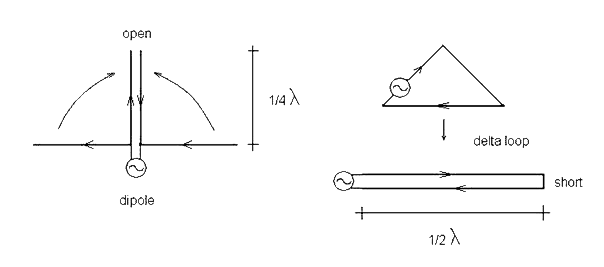
Deriving the conducted common mode input impedance of a center‑fed half‑wave dipole and an edge‑fed full‑wave delta loop. Source: ©2007 Jan Simons, PA0SIM
| input impedance | differential mode | common mode |
|---|---|---|
| center-fed half-wave dipole | low | low |
| full-wave loop | low | high |
| folded half-wave dipole | medium | high |
Differential mode antenna input impedance
The differential input impedance is normally what is meant when talking about the input impedance of an antenna. It is the antenna input impedance derived from treating the antenna as a lossy two‑wire transmission line in differential mode. The loss stems from the radiation resistance. As can be observed in Figure 1, the desired antenna currents are indeed equal but opposite when viewed from the source.
In differential mode, the legs of a half‑wave center‑fed dipole can be seen as a quarter‑wave long open‑wire transmission line. This transmission line is open at the end and transforms this open over its lossy quarter‑wave length to a low differential mode input impedance at the feed point.
Likewise, a full‑wave loop antenna behaves as a lossy half‑wave long open‑wire transmission line in differential mode, but with a short at its end. This equally transforms to a low differential mode input impedance at the feed point.
A folded half‑wave dipole behaves similar to a full‑wave loop, except that the radiation resistance gets quadrupled due to the additional transformative effect of this antenna type.
Common mode antenna input impedance
The (conducted) common mode input impedance of an antenna is derived from treating the antenna as a single‑wire transmission line in common mode.
In common mode, the legs of a half‑wave center‑fed dipole can be seen as a quarter‑wave long single‑wire transmission line. This transmission line is open at the end and transforms this over its quarter‑wave length to a low common mode input impedance at the feed point.
On the other hand, a full‑wave loop antenna behaves as a half‑wave long single‑wire transmission line in common mode, but with an open at its end. This transforms to a high common mode input impedance at the feed point. This explains why full‑wave antennas are less susceptible to receiving common mode noise.
The common‑mode input impedance of a folded half‑wave dipole is equally high for the very same reason. Even more interestingly, folded half‑wave dipoles can easily be made self‑balancing.2
Common mode on ladder line
Common mode currents can flow even through –supposedly balanced– open‑wire, twin line or ladder line. Naturally, this can be resolved by inserting a balanced common mode choke –or should it be called a balbal, in analogy with a balun and an unun?
However, ladder line common mode currents may also be resolved in a way that is not available for coaxial cable. The balun or balanced tuner feeding the ladder line forms a very high impedance for common code currents. If the feed line is an odd multiple of a quarter wavelength long, this high common mode impedance gets transformed to a very low common mode impedance. By consequence, common mode currents will flow through the feed line if the common mode antenna input impedance is also low.3 (See Table 1.) Therefore, ladder lines are best kept at multiples of a half wavelength for antennas with a low common mode input impedance (e.g. a half‑wave center‑fed dipole). Doing so, will present a very high common mode impedance at the antenna feed point, effectively suppressing common mode currents on the feed line.
There is even a third way, which suppresses magnetically induced common mode currents by replacing the balanced line with a star quad line. This is explained here.
Optimal placement
Before entering into detail about the construction of common mode chokes, their optimal placement will be discussed first.
TODO: Below information needs to be rewritten with regard of the two distinct common mode components.
A common mode choke employed at the feed point of an antenna, will attenuate only the conducted common mode component. This common mode choke will also constitute a new boundary condition for any induced common mode currents. Hence, a comon mode choke at the feed point of an antenna will render the two common mode components orthogonal relative to one another.
In most circumstances, both common mode components exist as a standing wave along the feed line. Therefore, for any given frequency, a common mode component will show current maxima every half wavelength;
- starting from the antenna feed point for the conducted common mode component, and
- starting from one quarter wavelength below the antenna feed point for the induced common mode component.
Without at least two common mode chokes placed at the respective location of a current maximum for each of the common mode components, common mode current maxima will continue to repeat further down the feed line. On a balanced transmission line, a well made balun may take on the role of a common mode choke. This is not the case for coaxial cable.
At its lowest employable frequency, a sheath current choke typically inserts only about 500 Ω impedance in series with the sheath of the coaxial cable. This means that sheath current chokes are ineffective at places along the feed line where the common mode wave has a current minimum, because the common mode impedance there will be high (typically several kΩ). Sheath current chokes are most effective at common mode current maxima (Figure 2); i.e. at a distance \(\frac{\lambda}{4}\) from the antenna ends and at odd multiples thereof: \(\frac{3\lambda}{4}\), \(\frac{5\lambda}{4}\), …
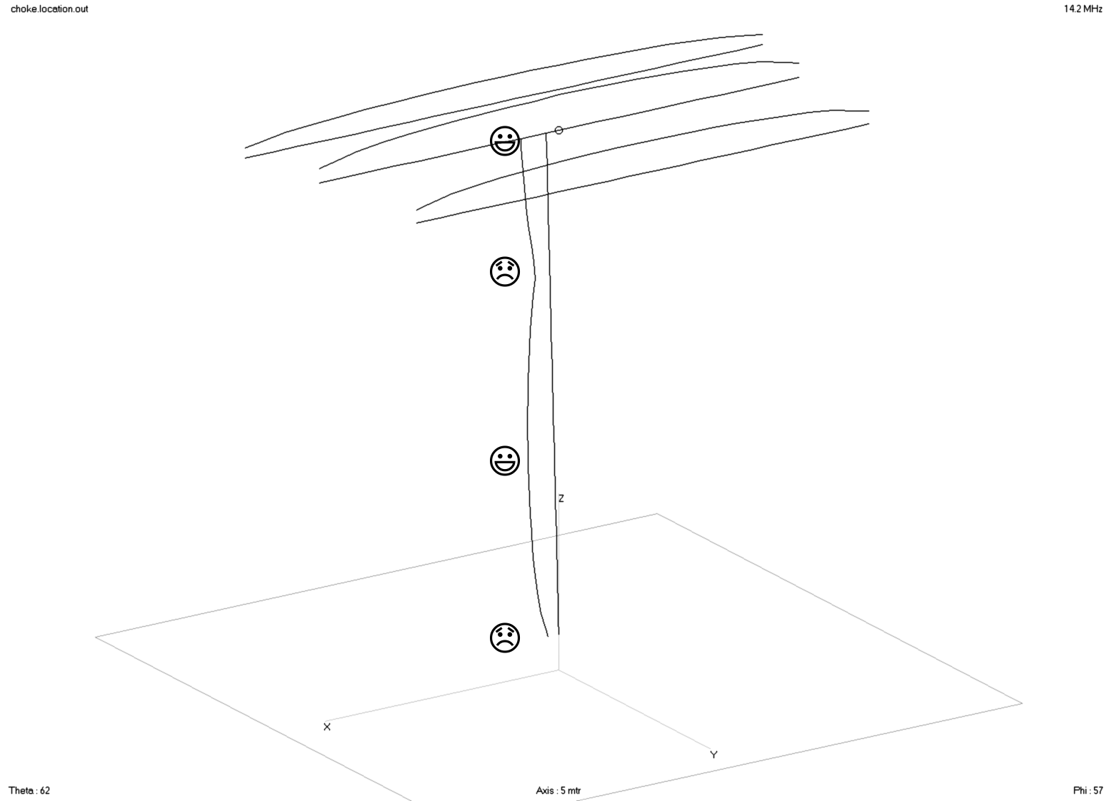
A coaxial feed line runs from a 3-element 20 m-band Yagi-Uda antenna at a height of about 15 m (50 ft) to the ground. No balun is being used. The curved lines are a measure for the currents on the antenna and the outer sheath of the coaxial cable. Current maxima along the coaxial line are good locations for inserting a sheath current choke. Current minima should be avoided. A current balun at the center of the feeding element should also be used with this type of antenna.
Practical considerations
By all means, use a decently made, properly rated (frequency and power) current balun at your antenna feed point. This will be a first, broadband defence against common mode sheath currents on the coax. For the sake of clarity; a current balun and a sheath current choke are two different devices. Both devices can be found combined in the same housing, but this is not very common.
A current balun tends to be less effective at lower frequencies because the common mode series impedance is produced from inductance as opposed to the changed boundary condition for surface waves created by the vicinity of ferrite material. Therefore, the common mode rejection of a current balun may not be sufficient for the connected coaxial cable at the lower frequency bands. An additional coaxial sheath current choke may be required at current maxima of the lowest frequency band. This is:
- at \(\frac{\lambda}{4}\) distance measured from the antenna ends, where \(\lambda\) is the wavelength of the lowest frequency band, and/or
- at odd multiples of this length, i.e. \(\frac{3\lambda}{4}\), \(\frac{5\lambda}{4}\), …
This will normally also handle the common mode wave rejection for the second lowest frequency band if this is a harmonic of the lowest.
Sheath current chokes close to the antenna feed point will help to preserve the radiation pattern of the antenna. Sheath current chokes closer to the shack may help better against RFI.
If you can, connect the coax sheath to earth at both ends and place the coaxial cable on or below ground.
Jim Brown, K9YC, produced a seminal work about common mode chokes. As a primer, reference work and cookbook it is an absolute must read!
The Guanella common mode choke
A Guanella common mode choke can best be described as a transmission line that selectively acts as a choke for common mode signals. It behaves as a transmission line for differential mode signals, but acts as a choke for common mode signals.
In his original publication, Swiss national Gustav Guanella also described his invention as a double wire choke or a coiled Lecher line; i.e. a coiled open wire line.
By virtue of fundamentally being a transmission line, Guanella elements maintain there desired characteristics over a much wider frequency range than ordinary broadband transformers.
The original Guanella element was a double wire choke in air; i.e. without any ferromagnetic core. Careful selection of a ferrite core material may greatly improve the common mode choking performance of a Guanella element. Ferrite material selection for choking is described in the following section.
TODO: Add a drawing. Describe the working principle.
Selecting ferrite core material for chokes
A ferrite material mix for choking is primarily selected for maximal absorption over the desired frequency span. It may also exhibit a high permeability \(\mu_{r}\) in this frequency range. However, as Steve Hunt, G3TXQ (SK) pointed out, a choke should always be more resistive than reactive at the frequencies of interest. If not, common mode currents may increase dramatically when the load becomes capacitive and enters into resonance with the choked transmission line.
For HF and in order of preference, Fair-Rite® material 31 (identical to Ferroxcube material 3S4) as well as Fair-Rite® and Amidon™ material 73 and its replacement material 77 are all very appropriate. This coincides with the recommendations of Palomar Engineers®.
| mix | material | µinitial | optimal choking | useful choking |
|---|---|---|---|---|
75 |
MnZn | 5000 | 150 kHz – 10 MHz | 10 – 30 MHz |
73 |
MnZn | 2500 | 100 kHz – 10 MHz | 10 – 30 MHz |
77 |
MnZn | 2000 | 100 kHz – 10 MHz | 10 – 30 MHz |
31 & 3S4 |
MnZn | 1500 | 1 – 10 MHz | 10 – 300 MHz |
43 |
NiZn | 800 | 30 – 300 MHz | 2 – 30 MHz |
52 |
NiZn | 250 | 200 MHz – 1 GHz | |
61 |
NiZn | 125 | 200 MHz – 2 GHz |
Quoting page 2-17 of the Amidon Tech Data Book:4
«The
43material is a good allround material for most RFI problems. However, the lower frequencies from 0.5 to 10 MHz can best be served with theJmaterial. The77material can provide excellent attenuation of RFI caused by amateur radio frequencies from 2 to 30 MHz. The43material is best for everything above 30 MHz. However, it is still very effective across the entire amateur band but not quite as good as the77material. The73material is specifically a ferrite bead material having a permeability of 2500 and can provide RF attenuation very similar to the77core material.»
Impedance versus frequency for a single wire through Fair-Rite® part number 26··540002 (9/16″ OD, 1/4″ ID & 1-1/8″ long core) made out of various ferrite mixes. Source: Cable Cores for EMI Suppression Copyright: Fair-Rite®
TODO: Add Sevick comment.5
Sourcing ferrite core material
Sourcing quality ferrite cores might be difficult outside the United States. In Europe, I found DARC Verlag to be offering an interesting selection for amateur radio use. Here is the specsheet. I also procured yet a different kind of small diameter ferrite toroids from the German company DX-Wire, which I use to construct my sheath current chokes (see next section). The company web site also publishes measurement results for different choke designs.
Maxwell sheath current choke
Walter Maxwell, W2DU (SK), first popularised a sheath current choke consisting out of a large number of ferrite toroids slid over the sheath of a coaxial cable (Figure 4). Black heat shrink can be used to keep the ferrite toroids in place.
This and below chokes are in fact all of them basic Guanella transmission line elements.
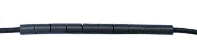
A W2DU (SK) or Maxwell sheath current choke prior to applying heat shrink.
Straight‑wound Guanella toroid choke
One could also simply wind RG-58, or even better, teflon dielectric RG-142 coax on a large toroid ferrite core to pursue the choking of common mode currents. However, Steve Hunt, G3TXQ, demonstrated with a nice set of measurements that straight-wound Guanella toroid chokes are reactive rather than resistive over large swathes of the frequency spectrum. At least three different such chokes are required to cover the extent of the HF spectrum. Steve also explains why choke reactance is undesired. Hence, their use is not preferred.
W1JR cross‑wound Guanella toroid choke
Joe Reisert, W1JR, first proposed a cross-wound coaxial Guanella toroid choke with reduced interwinding capacitance, limiting the risk of deleterious common mode resonances, whilst maintaining the resistance for the common mode. The cross winding has as additional benefit that the coax connections are at opposite ends of the toroid core. Thomas Tinge, PA1M, showcases a nice collection of homemade W1JR chokes on his web site. This type of common mode choke is recommended for most HF amateur radio applications.
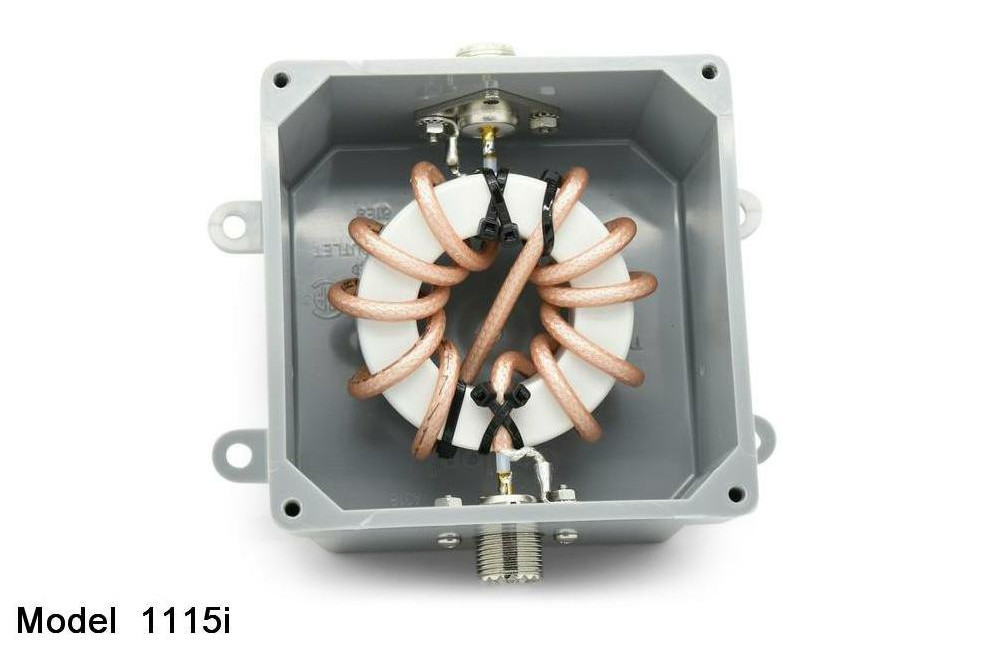
A W1JR cross‑wound Guanella toroid choke made by Balun Designs
Measuring choke impedances
Steve Hunt, G3TXQ, has devised a more precise method for measuring choke impedance using both ports on a VNA. He also published the mathematical derivation for this method and a helpful spreadsheet.
Nowadays, testing a toroidal ferrite core is really easy; put a wire through it and connect it to the measuring stand of a calibrated vector network analyser (VNA). Prior calibration is done using two paralleled high-precision 100 Ω resistors and the same wire without any ferrite clamp.
For a complete sheath current choke, the basic premise is to measure it like any other inductor. Measure the impedance between both ends of the coaxial screen at the lowest desired blocking frequency. This of course is only possible when the coaxial cable is not much longer than its enclosing choke. Measuring between the two center pins of the coaxial cable also works.
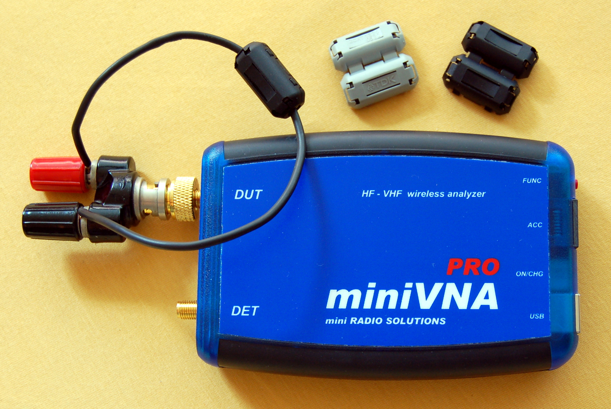
Choke testing with the miniVNA Pro over a wireless Bluetooth connection. The grey ferrite clamp is a TDK ZCAT 1325-0530A, the black ones are no-name counterfeit (see text).
Beware of counterfeit
Above-mentioned test procedure came in handy when I compared the quality of counterfeit no-name ferrite clamps against the original TDK ZCAT 1325-0530A (Figure 6). Chinese counterfeit was shipped despite ordering original TDK clamps from Wen Juntao, just_for_survive on eBay. Apart from the labelling, both type of clamps look the same. However, there are slight differences in the visual appearance and weight of the ferrite material. Impedance measurements with a calibrated miniVNA Pro revealed the Chinese knock‑offs to be consistently underperforming (Table 3 & Figure 7).
| \(f\,(\text{MHz})\) | \(\lvert\overline{Z}_\text{TDK}\rvert\,(\Omega)\) | \(\lvert\overline{Z}_\text{fake}\rvert\,(\Omega)\) | \(\Delta\) |
|---|---|---|---|
| 3.5 | 27.0 | 17.3 | -36% |
| 10 | 55.7 | 39.7 | -29% |
| 30 | 101.5 | 89.3 | -12% |
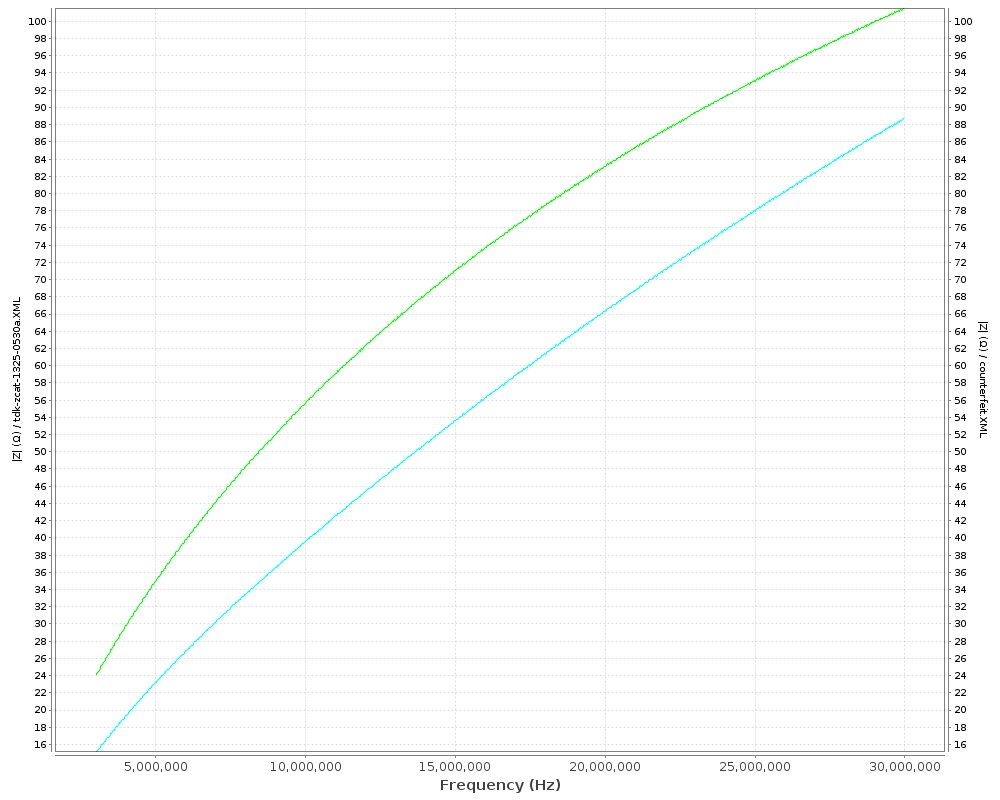
Measured impedance of ferrite clamps at HF; higher values are better. Green: original TDK ZCAT 1325-0530A; Cyan: no-name counterfeit
References
- Jim Brown, K9YC
- Guanella
- Steve Hunt, G3TXQ (SK)

This work is licensed under a Creative Commons Attribution‑NonCommercial‑ShareAlike 4.0 International License.
Other licensing available on request.

Unless otherwise stated, all originally authored software on this site is licensed under the terms of GNU GPL version 3.
This static web site has no backend database.
Hence, no personal data is collected and GDPR compliance is met.
Moreover, this domain does not set any first party cookies.
All Google ads shown on this web site are, irrespective of your location,
restricted in data processing to meet compliance with the CCPA and GDPR.
However, Google AdSense may set third party cookies for traffic analysis and
use JavaScript to obtain a unique set of browser data.
Your browser can be configured to block third party cookies.
Furthermore, installing an ad blocker like EFF's Privacy Badger
will block the JavaScript of ads.
Google's ad policies can be found here.
transcoded by


 .
.

